FAQ pCon.planner
Table of Contents

What is the difference between the application language and the data language in pCon.planner?
The user interface of pCon.planner can be displayed in different languages. The settings for the language of the commercial data are to be distinguished from the application language. These affect the data and, in some cases, offer forms that you use in pCon.planner.
Application and data language can differ from each other. They are set independently from each other:
Set new application language
- Set application language under File > Settings > General tab > User Interface > Language.
- Confirm by clicking OK.
- Restart pCon.planner to have the user interface displayed in the new language.
Set new data language
- Open Products catalog.
- Click the cogwheel icon to open the Catalog Settings.
- Open the Miscellaneous tab in the Catalog Settings.
- Set languages and confirm by clicking OK.
Note: Catalog Languages and Article Languages can be set separately.
The catalog language affects the display of all texts in the OFML product catalog. The Article Language affects all texts for OFML articles (properties, product information and relevant product data in the article list or forms). The setting option Standard is primarily based on the selected application language.
Note: A second language can be defined via the Secondary language selection. The pCon.planner uses this language if the primary language is not available in the catalog data.
More details this can be found here:
https://help.pcon-planner.com/en/help/settings.htm
https://help.pcon-planner.com/en/help/manufacturer_catalogs.htm
How do I create and use templates?
Template files are used to start new drawings with predefined content and settings.
Templates are saved in the DWT file format and can contain all aspects of a drawing that are saved directly with a drawing file. These include:
- Drawing elements like floor plans, rooms or room elements
- Predefined layout pages with viewports and stamps
- Document properties
How do I create a template?
- Open a new drawing.
- Insert drawing elements, define document properties etc.
- File à Save as à Enter file name à File type: select Drawing Template (*.dwt).
How do I load a template?
- Open the File menu.
- Click on Templates.
- Select a template file from your file system.
- Confirm by clicking Open.
- Safe as DWG file under a new name and continue planning as usual.
Store templates in the program settings
You can store a DWT file as standard template. This is then automatically loaded each time pCon.planner is started and a new plan is created.
This way you can access your predefined settings and configurations for document properties, layout templates and more.
The template stored in the program settings is not used for the currently opened drawing. The template will also not be loaded when old drawings are opened.
How do I keep the file size down when creating a drawing?
Complex drawings can reach an enormous file size. The pCon.planner does not set a strict maximum size for the files in use. The interaction between very large drawings and the individual hardware equipment of your system can lead to problems during the planning process. For example, saving and loading plans can be prevented if there is not enough free working memory available.
To avoid this, follow these instructions during the planning process:
Using external 3D geometries
Models from free internet databases vary in size and quality. If possible, make sure to insert geometries with small file sizes into your planning.
Use Groups
Geometries are always imported as a group. In order to edit individual elements of a group, it may be necessary to ungroup it first. After the editing steps, it is essential to regroup the geometries – and especially if these geometries are used several times in a planning.
To do this, select all elements of the group and use the Group command (Edit tab).
Grouping avoids unnecessary duplication of the contained geometries when copying the geometry groups. This saves memory and file size.
Group as many elements as possible
In general, grouping elements in your drawing is a good way to reduce the number of objects at the highest planning level and thus the size of the file.
Use reference copies instead of real copies
A specific manufacturer article is often used several times per planning (keyword: open space office). In this case, it is recommended to insert the article into the planning once and then copy it as often as necessary using the Reference copy command (Edit tab).
In comparison with real copies, working with reference copies drastically reduces the file size.
Another advantage: if a copy is modified in its properties, all its references are automatically adjusted.
How can I prepare my design for an architect?
Planning data must be processed by various involved parties/service providers in the course of a project. The variety of software solutions available on the market may require converting the data into a different format.
pCon.planner offers various export options to achieve the best possible compatibility. However, the amount of geometry of 3D models is much higher compared to pure 2D data. Experience has shown that not all programs can handle such data volumes well, so that problems sometimes occur when importing data from pCon.planner into another application. Our software therefore offers options for preparing plans before they are passed on to architects, for example.
To create a 2D floor plan based on a 3D plan without any 3D information, there are the following possibilities, depending on the required level of detail:
1. use the extended DWG export
The extended export dialog for DWG files increases the compatibility of your DWG files with external programs.
You can access the dialog by going to File > Export > Geometry in pCon.planner, assigning a file name, and confirming.
In the “Modify” section, you can activate various reduction options:
– Remove 3D geometry
– Reduce layers
– Remove add-ons
Enabling all 3 options will remove a maximum of 3D content, and optimize the file as much as possible.
Please note that elements without 2D representation, e.g. simple geometry types like cuboids or elements from the 3D Warehouse, will not be included in the exported file.
If these elements are required, a 2D representation must be generated manually in advance. The 2D Projection option in the Edit tab under Tools is suitable for this purpose. The 2D projection can also be generated from several selected elements at the same time. It is useful to put the generated 2D representation on a separate layer, e.g. “2D Projection Decoration”.
2. creating a vector export from the “Top” view
Set the “Top” view in the open planning in a work area (menu at the top left of the window) and adjust the image section to your requirements.
Tip: Double-clicking in an empty planning area centers the view on the complete planning.
Now set the display to wireframe mode in the View tab and check the display. If necessary, adjust the planning by hiding elements.
If you are satisfied with the display and the image section, switch to the “Presentation” tab and select the “Vector graphic” entry.
In the render dialog that opens, set “Wireframe” as the renderer. If desired, you can also adjust the settings for line width and color.
Click on the green start button to generate a corresponding rendering, which you can save in various formats by clicking on the save button.
3. manual removal of 3D data
Create a new file from the project to keep the original planning for further processing.
Step by step, hide or delete all labels and other elements outside the planning that are not needed.
Now the 3D planes are hidden or deleted. Here you must check whether a 2D representation of all required elements is available (if necessary, create it later, e.g. using the 2D projection). The following should be noted:
3D planes that correspond to our naming scheme (*_D3_*) can be selected and edited via the filter settings in the plane manager.
Geometries whose planes do not follow the pCon.planner naming scheme cannot be assigned automatically. They must be hidden/deleted manually.
After successfully deleting all 3D elements, you should run the purge function, and then save the file.
Now, for example, a vector export (Presentation tab) can be created and saved as a PDF, or a further reduced file can be created via File > Export > Geometry.
If you want a pure 2D result, it is necessary to remove all 3D elements from the design beforehand.
Otherwise, the hidden 3D layers would no longer be visible, but still remain in the planning, and there would be hardly any effect on the file size.
Alternatively, individual elements and layers can be saved separately:
1. select element(s) directly in the planning and create a new file via File > Save Selection.
2. select objects of the layer via the layer dialog (if required, all furniture of a category/area etc. can be placed on a (new) layer in advance, and create a new file via File > Save Selection.
How can I use content from the pCon.planner for my Microsoft PowerPoint presentation?
With Office 2019 or Office 365 it is possible to insert and use 3D models directly in Microsoft Office:
- Select the desired objects in the planning.
- In the Clipboard section of the Start tab, click Copy and select the entry 3D Model Microsoft. Now the element is in the clipboard as a gltf file.
- In Microsoft PowerPoint, you can now insert the element into your presentation by clicking Paste.
- Since the element is inserted as a 3D model, you can edit it directly in Microsoft Office (rotate, align, animate, …).
How can I zoom through walls when navigating?
When navigating in pCon.planner, it happens that you get “stuck” in walls and other objects. Zooming is only possible very slowly until you are out of the object again at some point.
In this case, the key combination Shift + Zoom will help. This allows you to move through objects with normal zoom speed.
Where can I find additional room accessories for my planning?
Additional furnishings and decorative elements add the finishing touches to your plans. Suitable 3D models can be found, for example, from these services:
Sketchfab
Free registration, partly free models in very good quality and various common file formats
https://sketchfab.com/3d-models
Trimble Inc® 3D Warehouse
free models in SKP format, own pCon.collection especially for users of the pCon.planner
There are also databases for 3D models on many different topics.
Download third-party models into your local file system and insert them into your planning by drag&drop or via the Media Browser (on the toolbar on the right-hand side of the pCon.planner).
An overview of which 3D formats you can import into the pCon.planner can be found here.
Why do glass materials or the objects behind them appear black or gray in photorealistic images?
Problem
Glass objects and the objects behind them appear as black or grey in photorealistic renderings.
Background
This issue is connected to the ray depth used for the rendering process. The ray depth determines how often a ray of light is reflected within the scene.
If your planning contains many translucent or glass objects, the default ray depth will not send enough rays of light through the glass. This leads to a less realistic look of these glass objects. A higher value for ray depth will send the ray of light through the scene repeatedly.
Solution
Enter a higher value for Ray Depth (Ray Depth 10). In addition it can be useful to reduce the Refraction Index for your glass material to 1 (in the Material Editor under Transparency). This way, all rays will go through the glass instead of being reflected at the surface.
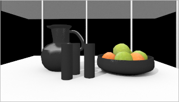 | 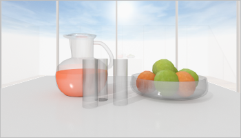 |
| Rendered with OSPRay; Ray Depth 1 | Rendered with OSPRay; Ray Depth 10 |
Parts of my planning are not visible. How do I bring them back on screen?
Problem
After you have opened a planning or selected another projection during the planning process, parts of your drawing are no longer visible.
Background
There are two possible reasons for this issue:
- Whenever you start pCon.planner, you are at first working with the World Coordinate System (WCS). It marks the point of origin for your planning. Neither origin nor orientation is susceptible of alteration. It is possible that you start your planning process far away from the WCS point of origin, either by using the User Coordinate System (UCS) or by starting the drawing process while in perspective view. Read more on WCS and UCS here.
- In pCon.planner, two- and three-dimensional objects are filed on different layers. If elements of your planning are invisible within your working area, this can be due to your layer settings.
Solutions
- Please try CTRL+SPACE to display all objects contained in the planning in all work areas. This way you will detect dislocated fragments and will be able to select and move or delete them. In case you have previously worked with the USC, please reset the WCS. To do so, please use the C key. Alternatively, right-click the workspace and select Set WCS Origin from the context menu. After this, select all objects in your planning and move them to the WCS origin.
- Please open the Layer dialog to check whether all layers in your planning are active and visible. If a layer is marked with the inactive symbol (a crossed out eye) it is invisible in your work area. Klick the symbol to mark the layer as visible. Read more on layer management here.
What is a backup file and how do I use it?
Backup files ensure that your plans are not lost should pCon.planner crash. pCon.planner automatically creates a backup file for your current plan – as long as you haven’t disabled this option in the Program Settings. We recommend leaving the automatic creation of backup files enabled. You should also set an interval for how often pCon.planner saves the backup file. For this, we recommend an interval of 10 minutes. With the option Use common folder for backups, you can specify a location for all backup files, independent from the original file’s folder. Especially if you are working in a team, exchanging DWGs over a company network, or frequently changing the location you work, you should set a folder on your local hard drive. | 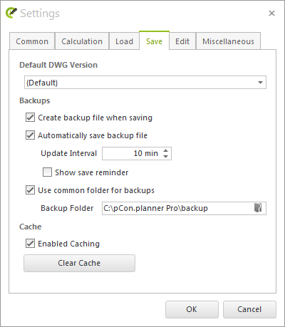 |
What should I consider when disabling High Quality Printing?
Background
When printing view ports in the Layout area and in Print Preview, the High Quality Printing option is enabled by default. A mixed process is used for printing: visible lines, edges, dots, hatching and fonts are based on vectors. With vector printing, these elements remain sharp, even when greatly enlarged. Colors and textures are printed as images.
To disable High Quality Printing, remove the check mark from this option in the Properties Editor. The result will be pure image printing. The demand for memory and the file size of printed PDFs will then be lower, but at the expense of print quality.
Note
If High Quality Printing is disabled, you can still positively influence the print quality by setting the Image Resolution to dpi in the advanced Layout Settings.
There you can choose between various preset values. The upper limit is 600 dpi. It is possible to manually set a higher dpi value, but this is not advisable. An extremely high Image Resolution uses too much memory and processes may no longer run smoothly.
Why are images or textures blurred or pixelated?
Problem
You inserted a floor plan as an image and it appears blurred or pixelated.
Background
pCon.planner will display images and textures up to a maximum resolution of 2048×2048 pixels in good quality. If you insert an image larger than this, the program will undercalculate the resolution and the image may no longer appear clear. The display depends on the content of the image. Fine lines, for example, are more affected than colored areas. Floor plans, in particular, should therefore be imported in a suitable resolution. This restriction works to keep the size of the plan low, saving both internal and graphics memory.
Solution
To ensure high-quality images and textures, follow the below instructions:
- Select images with a maximum size of 2048×2048 pixels.
- Scan floor plans in an appropriate resolution (i.e. 150 dpi)
- Before you insert larger images into pCon.planner, edit them in a suitable image editing program. Change the height and width so that they fit to our suggested limits.
- If you use high-resolution images as textures, set the Texture Quality to Extra High. To find the Texture Quality, go to the ribbon, switch to the View tab and open the Render Settings (click on the circled arrow). In the Render Settings dialog, switch to the Quality tab. A Texture Quality with a high setting means, however, that pCon.planner will use more graphics card memory.
Note: pCon.planner only reduces the image resolution for the display. This does not have an affect on the quality of photorealistic renderings, exports or printouts/PDFs.
What is the difference between Scaling Unit, Length Unit and Insert Unit?
When working with pCon.planner, there are various tasks involving units that are important:
- Default Scaling Unit (Application Menu, Settings button, Load tab)
- Length Unit (Application Menu, Settings button, Edit tab)
- Insert Unit (Application Menu, Document Properties button, Settings tab)
Each of these three units have different effects
The Default Scaling Unit – also known as the Scaling Unit – is necessary when you want to insert objects of an unknown scale. The Length Unit describes the standard when inputting the measure of length. The Insert Unit has an effect when you want to use plans created in another CAD program. Click on the respective unit for more detailed information.
Example:
- The Default Scaling Unit changes the scaling of imported geometic objects as well as from plans with unknown units and objects that you insert from the media browser.
- The Length Unit influences the unit of the values in the input field during planning. The selected unit of length has no affect on your dimensions.
- Changing the Insert Unit has an affect on proportions when drawing walls, for example. Dimension values will stay the same – the changed unit will be used in the background, however pCon.planner will not convert the values.
Why can’t I access my manufacturer’s catalogs?
Problem
You are a pCon.planner PRO user. Following an update, the installed manufacturer’s catalogs are no longer available. The Products button on the Toolbar (right-hand side) is missing.
Background
It is likely that you installed the free version of pCon.planner. To check, look at the top (on the title bar) of the program window. There you can read whether the currently-installed edition is pCon.planner (the free version) or pCon.planner PRO (the professional edition). Please bear in mind that a data connection in the free version of pCon.planner is not possible.
Solution
Install the current PRO version. To do so, please contact your EasternGrapics business partner or simply download pCon.planner PRO.
How do I change my unit of measure?
Changing the Unit of Measure via the Dimension Styles Dialog
If you would like to view the dimensions in a different unit, proceed as follows:
- Switch to the Edit tab on the ribbon.
- Open the Dimension Styles dialog.
- Adjust the Unit for your current dimension style (available in both the free and PRO versions of pCon.planner).
Example
You would like your dimensions shown in millimeters. Set the Unit to Millimeter. The height of a baseboard measuring 0,1 meters should now be shown as 100.
The changes will influence all dimensions within the plan that use this Dimension Style.
Changing the Unit of Measure for individual Dimensions
If you want to change the unit of measure for a single dimension, proceed as follows: Select the dimension and open the Properties editor. Under the Unit of Measure option, set the unit you want to use. This will change the unit for the selected dimension. All other dimensions within the plan remain unchanged.
Separate Dimension Styles for Planning and Layout Area
The dimension style is selected separately in the design and layout areas.
The unit of measurement is based on
- Planning area: the insert unit of the drawing (Application menu, Document Settings, Settings tab)
- Layout area: Length Unit (Layout Settings, Operation tab)
Due to the differing units, the styles should usually only be used in one of the areas. Therefore, separate dimension styles must be defined for the planning and the layout area.
Two appropriate styles are predefined accordingly:
- X3G_BASE_DIM_STYLE – planning area
- X3G_Layout_DIM_STYLE – layout area
What is the Length Unit and where can I change it?
Under Length Unit, you can set the standardized unit in which you enter values in pCon.planner.
This can be changed through the Application Menu. Click on Settings and switch to the Edit tab.
Example: You set the Length Unit as Meter. Now, you want to change an object to 5 centimeters. To do so, you have two options:
1. Enter 0,05
2. Enter 5cm.
Both entries will have the same result: Your object will change to 5 cm.
Note
The Length Unit does not affect dimensions. To learn how to work with dimensions and how to change them, you can read more in the pCon.planner Help or here.
How do I correctly insert objects of unknown scale into pCon.planner?
The Standard Scaling Unit or Scaling Unit is relevant for objects with unknown scaling that have been inserted into pCon.planner. This can be set through the Application Menu. Click on Settings and switch to the Load tab.
If the option Use this scaling unit by default: is activated, the selected unit will be applied to the dimensions for 3D elements of unknown scale.
Note
A conversion of the values will not be carried out. That means that newly-inserted objects may not fit to the dimensions of your plan. When inserting objects with unknown dimensions, we recommend the option Show scaling unit selection dialog when opening geometry with unknown scaling.
pCon.planner will then show the Scaling dialog during insertion. Here you can change the width, height and depth of the object so that it fits to the proportions of your plan.
The walls in my plan are no longer connected. How do I fix this?
Problem
During the planning process, you may accidently break the connection between two walls. When this happens, you will recognize that the corners are no longer aligned, but form a gap instead. Often times, you will continue to work on the plan before you realize that the walls are no longer connected. Because of this, the Undo button will not usually solve the problem.
Solution
- Select the two affected walls.
- Switch to the Start tab on the ribbon.
- Click on the button Wall Tools in the Room Elements group. This will open a menu.
- Select the Connect command. The walls will then be connected once again.

Can animations be computed into compressed video files with pCon.planner?
Videos can be generated in two ways: Either directly in pCon.planner as compressed video or by passing it on to EGR-BatchRendering, with subsequent compression and editing in an external video program. The external video calculation can comfortably run in the background while you continue working with pCon.planner.
For the external calculation as well as for the video processing in pCon.planner, a compression method can be selected that reduces the size of the corresponding video. However, pCon.planner itself does not provide codecs. The application accesses the video codecs installed in the system. We recommend the codec x264vfw, which can be downloaded free of charge via this link.
If you want to use compression methods that are not yet available on your system, you need to make sure that the codec you are installing was developed for Video for Windows (vfw). Only then the pCon.planner can access it and offer it in the selection list when saving the video.
Video processing in the pCon.planner
Note: Animations that have been calculated with EGR-BatchRendering cannot be converted to a video in pCon.planner.
- Calculate your animation using the Video button on the Presentation tab.
- After completion, click on the Save As button in the Media Output dialog.
- In the Save As dialog that opens, select Video Files (*.avi) under File Type and enter the desired file name.
- After clicking the Save button, the Select Video Compression dialog opens. Select the entry x264vfw – H.264/MPEG-4 AVC Codec.
- The Options button takes you to the advanced codec settings. Pay attention to the following settings: Zero Latency should be activated, and in the Rate control section one of the Single pass modes should be selected.
- Save these settings and click OK button to calculate your video.
External Video Processing
As an external video program with editing options and various codecs to compress the video size we recommend Avidemux, which can be downloaded free of charge here: Avidemux
Can I optimize the performance of pCon.planner?
Background
In combination with older graphics hardware, limitations are possible while working with pCon.planner.
Solution
There is a variety of ways in which you may be able to improve the performance of the design application:
- The Render Settings are to be found in the Render group on the View tab – click the icon on the right along the lower edge. When the dialog opens, change over to the Quality tab. Set Textual Quality to Simple and the Shadow Quality to Off.
- On the Edit tab in the Program Settings there are two items relating to synchronization: they are Synchronize centers in orthographic views and Synchronize fields of view in orthographic views. Both should be disabled if the graphic performance is weak.
- Program Settings, tab Miscellaneous: The Level of Detail option influences the quality of solids in planning. A high value improves the graphical display of these objects, but may have a negative effect on performance. Therefore, you should select a low level of detail if the graphics performance is weak.
- You should avoid opening pCon.planner more than once, as the hardware resources required would then have to be shared rather than simply being available to the one instance.
- When you are using your computer to operate pCon.planner, do not use any other 3D applications at the same time. They will make demands on the same hardware resources, and performance will be reduced for whichever you are trying to use.
- Work in one window without subdividing into a number of viewports.
- Reducing the size of the screen area used for the software on your monitor will mean the graphics are computed faster.
- Make sure you have the latest graphics card drivers (if possible not older than 1 year). You can usually find them on the websites of the respective graphics card manufacturer.
Note
There may also be some loss of performance if the current design is very large and complex, in which case we recommend the same solutions as suggested above.
| Note: On our Youtube channel you will find a video on this topic: How to optimize graphics settings for smoother performance |
Why can’t I see any 2D objects in certain views?
Problem
2D elements such as drawing elements, images and texts are no longer visible when the view is changed, to Top or Right, for instance. They will, however, be displayed in other views.
Background
The elements will also continue to be present in the views you are using, but they will only be displayed in a perspective or isometric view or for example in Front or Rear view. This is because they differ from three-dimensional objects in possessing no information on depth as they are two-dimensional. They will thus not always be shown in Top view or certain other 2D views.
Solution
- Use multiple viewports simultaneously. Set one of your viewports to perspective projection. The object will be visible in this view so that you can select it. The selection will be shown in all viewports, so that you can locate your objects in your 2D views, as well.
- Change to the View tab. Open the Render mode menu and enable the Show Outlines option. This option marks all texts, images and 2D drawing elements with visible outlines.
- Change the Render mode. The problem does not arise for any 2D drawing elements in the Wire Frame, Hidden Line and Colored.
- For images, the Properties Editor has an option called Hide Border. Please select the image (from a view in which it is still visible, for example a perspective view) and open the Properties Editor. If Hide Border is activated, please deactivate it.
Why are images or textures blurred or pixelated?
Problem
You inserted a floor plan as an image and it appears blurred or pixelated.
Background
There are two possible causes for this:
- The resolution of the image is too low. Especially if a lot of detail is included in the image, it will appear blurred in the output.
- The Texture Quality in the pCon.planner display settings is set too low.
Solution
To ensure high-quality images and textures, follow the below instructions:
- Select images with a sufficiently high size (for example 2048×2048 pixels for detailed images).
- If you use high-resolution images as textures, set the Texture Quality to Extra High. To find the Texture Quality, go to the ribbon, switch to the View tab and open the Render Settings (click on the circled arrow). In the Render Settings dialog, switch to the Quality tab. A Texture Quality with a high setting means, however, that pCon.planner will use more graphics card memory.
What requirements does pCon.planner place on my graphics equipment?
Please make sure that your graphics hardware matches our system requirements. Also consider the following points:
Get up-to-date graphics card drivers
Graphics card drivers control the interaction between your system and the installed graphics card. The newer the driver, the smoother the communication between the graphics components and your system. An up-to-date driver therefore also optimizes the performance of pCon.planner.
This is how to find out which graphics card is installed in your system (instructions for Windows 10 as well as Windows 11):
- Type Device Manager in the search field of your Windows taskbar.
- The Device Manager will open.
- Look for Graphics Card and double click to open it. You should now see the graphics cards for your system.
Update the graphics driver as follows:
- Open the Context menu by right clicking on the Graphics Card entry.
- Click Update Driver.
- When the window opens, select Search automatically for updated driver software.
Note: The latest drivers are not always automatically installed. The current graphics driver can be found on your graphic card manufacturers website.
Use pCon.planner with a dedicated 3d graphics card
For an ideal performance of pCon.planner, we recommend using a dedicated 3d graphics card. These are cards with a powerful processor (GPU) and an extensive graphics memory. They are designed for use with 3D software such as pCon.planner.
If you have a hybrid system combining an onboard graphics card and a dedicated 3D graphics card, you should check whether pCon.planner is actually working with the 3D graphics card.
Our blog contains sample instructions on how to assign NVIDIA or AMD 3D graphics processors to pCon.planner.
Please note: If your notebook is not connected to an external power source, this can prevent pCon.planner from using the 3D graphics card. In battery mode, there is often an automatic switch from the power-intensive 3D graphics processor to the onboard card.
Please also ensure that the monitor is connected to the external graphics card. Otherwise, it cannot be assigned.
Workaround for the use of less powerful graphics hardware
If you only have an integrated onboard solution (integrated graphics card) available, working with pCon.planner will only be possible with certain restrictions. pCon.planner offers a software rendering mode to support onboard systems:
Please keep in mind that the following functions are not available in this mode: · Render styles Concept and Realistic · Antialiasing for real-time display · the virtual sky |
Please note: Software Rendering mode cannot guarantee the executability of pCon.planner on all systems. This is influenced by the performance characteristics of the available hardware and the complexity of the created design.
How can I change the licensing system for pCon.planner PRO?
Problem
I want to use pCon.planner PRO with the alternative licensing system, utilizing a conventional single-user or network license. Upon starting the program, I entered my user credentials for pCon.login. Now I can no longer access my alternative license.
Solution 1:
This takes effect if you can still start pCon.planner PRO with your trial license.
- Open the Help tab in pCon.planner.
- Click License
- Select license system dialog: Activate radio button Use alternative licensing system.
- In the same dialog, click on Manage licenses.
- The Safenet License Manager Click the Activate button.
- Enter license key. Confirm by clicking Activate.
- Confirm again by clicking OK in the Select license system
Solution 2:
This scenario takes effect if the test license for pCon.planner has already expired and the program will no longer start. In this case, you open the Safenet License Manager directly.
- The Safenet License Manager is stored in your local file system under c:\Program Files (x86)\EasternGraphics\EGR-SafenetActivation\.
- Open the folder and start SafenetActivation.exe.
- The dialog Safenet License Manager Click the Activate button.
- Enter license key. Confirm by clicking Activate.
Does pCon.planner also work in the Mac systems and with macOS?
Currently, we do not offer an official version of our application pCon.planner for Mac systems. Therefore, we do not provide support for this application under macOS.
Any use in such scenarios is therefore excluded from the warranty.
Currently, it is only possible to use pCon.planner on Mac systems by working with Windows virtualization. Please note that this type of use is at your own risk and without our support.
We are aware of the desire for an official version of pCon.planner for macOS. As soon as we have news about such an edition of pCon.planner, we will inform you in our pCon.blog: https://www.easterngraphics.com/pcon/en/